SVIF-T Supervision Control Interface
Contents
Introduction
SVIF-T uses a simplified version of the RS232 serial interface, and is thus easy to connect to almost any computer. From PCs or workstations down to 8-bit microcontrollers, almost all of them have a serial port or at least have the possibility to add one att very low cost.
The protocol used is "open" - it is therefore possible to merge it into your application software. This process is further simplified by sample source code and tools for testing being available for free.
Background
The start of SVIF-T happened more than 10 years ago...
After having worked for several years within several companies regading
supervsion -interaces and -protocols, this idea of a much lower cost and
general interface was born.
The letters of SVIF-T come from "SuperVison InterFace - Telecom grade". The word "telecom" is here used to indicate:
- that SVIF-T is optimised for large systems built on a single Signal Reference Potential Plane (SRPP) and the cable lengths and noise levels that are typical for such installations.
- that it is very easy to introduce redundancy - it is thus possible to build very high availability ("carrier grade") applications.
This requirement picture is however common to most electronic systems today, not only telecom.
SVIF-T is an "open" interface, meaning:
- its specifications are freely available from here - in the form of a "Physical Interface and Framing"
spacification and a separate "Message
Format" specification.
- that there will be reference
source code for generic message handling available and also a set of simple tools for testing and evaluation - see this link.
The license for use of the above
documents and code will be identical or close to LGPL - ie. free for use, copy
and modify provided its origin and modifications are always stated.
Physical Interface
Physically, each unit implementing SVIF-T always has two shielded RJ12 (6-pole modular) connectors, used according to the following:
- Pin1: +Power (+7-10V)
- Pin2: TD (Serial 9600Baud output with RS232 levels)
- Pin3: Ground (SRPP)
- Pin4: RD (Serial 9600Baud input with RS232 levels)
- Pin5: through connected connector 1 - connector 2
- Pin6: through connected connector 1 - connector 2
- shield: Ground (SRPP)
All cables have pins 2 and 3 crossed, but are otherwise stright connected.
Up to 255 units can be interconnected in a daisy chain, which can be supervised/controlled from one or both (redundant applications) ends.
Most units also have a LED. It is normally lit green, but can be controlled to blinking red (B-alarm) or fix red (A-alarm) illumination.
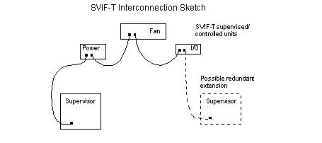
The connection between the units is made in the form of a daisy chain as shown in the figure above.
If the chain is supervised/controlled from only one end, the availability is comparable to any normal bus structure.
If however supervision is made from both ends of the chain, no single fault can harm the supervision.
Software Protocol
To describe the entire protocol her would take too much space. Instead we just list som of the important properties of the protocol:
- It is of request/response type, where the communication is initiated by the supervisor (with few exceptions).
- It is compact, though it has many functions. This has been achieved by a simple form of compression.
- It is object oriented, and can be extended by new classes if so needed.
Classes for handling of status flags, bit sense/control and measured values
exist, and will function the same regardles of other extensions.
- These classes provide a simple abstraction - the supervisor need not
know which bits of registers represent certain faults, supervision is
possible anyhow.
- It has four
adressing modes: absolute, relative and broadcasts. The relative adressmode uses
number of "hops along the chain", and thus requires no configuration (cabling
defines the adress).
Classification of failure flags are part of the
protocol - the recommended interpretation of this classification
is:
- A-alarm: Requires (immidiate) attention. The fault may affect the
operation of the system.
- B-alarm: Measures can wait until next regular
service. The failure does not have any system level impact due to redundance or
similar.
- neither A- eller B- alarm: No fault. This is just an informative
indication.